HVAC-Talk: Heating, Air & Refrigeration Discussion banner
1 - 20 of 65 Posts

DDCSD

· Professional Member
Joined
·
478 Posts
Discussion starter · #1 ·
Me again!

We have a 110 ton McQuay air-cooled chiller on campus serving a classroom/office building that trips on low flow or low evap temp fairly often. I've learned quite a bit from you guys about hydronics piping since I started working here, but this on is a little different than most of our other systems. Seems to happen at fairly random times and I've only observed it last fall and now in the last couple weeks. From viewing the trend data in the BAS, it appears to usually not make it through an entire day.

I'm currently waiting on O-rings to pull the strainers on the pump diffusers (as I'm sure it has never been done before), so I thought I'd come on here to try and understand the piping of a system like this better.

Little history:

5 years ago the building had a major overhaul where most everything in the CHWS was replaced except for the piping (including the chiller and pumps). Sounds like the chiller has been an issue pretty much since then. A co-worker mentioned something about the chiller control board being changed out and a strainer being cleaned multiple times. Have no records to look at from this time period, so pretty much starting from scratch here.

In looking at the system, the piping seems to be different than what I'm finding on piping examples from various sources.

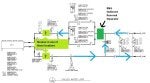
Here is what we have:


I honestly can't remember right now which side of the chiller the light green strainer is on. I'm not even sure right now what kind of strainer it is exactly. I think this is the one that my co-worker was talking about being cleaned out because the insulation has obviously been redone since it was installed.

The B&G SRS has a compression tank fitted with an airtrol fitting attached to the air removal port. Instructions for the SRS show it as needing to be installed just before the pumps, ours has the chiller between it and the pumps. Is this set-up OK or should it be changed?

The pumps currently pump "away" from the chiller. Every piping diagram I can find on variable primary systems with a bypass show the pumps pumping "into" the chiller. Which way is best (does it make a difference)? In my head, the by-pass would work better if the system was pumping "into" it instead of "pulling" it through the chiller and this could possibly be part of the flow issue. Or am I over-thinking it like usual?


From what I've read, it seems like the system should flow this way and the SRS should be moved:


Here is the SoO for the system.


Chiller minimum flow is 170 GPM

It is a McQuay AGZ125CHSNN-ER10

S/N: STNU100300221

Sticker on unit says it has Benshaw controls. Our BAS is Siemens Apogee and it communicates with the chiller VIA BACNET.


Being primarily a classroom building, there can be a very low heat load in this building at times during the day. A couple times that I noted a few times in the alarm history was around 1130am and 230pm. Might coincide with classes letting out and the building more or less being empty, but I haven't looked that far into it yet.


Am I right to suspect the piping to be an issue or do you think the strainers and low heat load are the most likely culprit? If it's mostly due to the low heat load, any suggestions on a work-around? The only reheat in the building is VAV's supplied from heat recovery our data center Lieberts.
 
Discussion starter · #5 ·
Is this a DX chiller?

I dislike varying fluid flow through a chiller as it makes it hard to achieve stabilized operation at anything other than full flow rate.

Did the previous system have a primary and a secondary loop? With independent pumps?

I like substantial buffer tanks but even an H connection would be better than nothing.

PHM
------
I want to make sure we're on the same page with the term DX chiller. Do you mean a chiller with a remote evaporator in the building, or an air cooled chiller? I'm still not great with some of the terms!

The current chiller has the chilled loop piped outside to the unit that had an on-board evaporator. The previous chiller had the refrigerant lines piped into the building where the evaporator was located. It is air-cooled.

Looking at the demo page in the prints, the previous system was primary/secondary with two chilled water system pump (duplex) and a separate evaporator loop.

The current system is set-up so that the bypass is supposed to maintain ~175 through the chiller by modulating that bypass valve.

Sent from my MotoG3 using Tapatalk
 
Discussion starter · #6 ·
Make sure the flow meter is reading the correct flow, may be out of calibration.
Would like to see the minimum flow valve farther way from the chiller , so when it opens it gets to mix with more of the return. This will help keep cold water from hitting the chiller. Check to see if bypass valve is the right size for the 175 gpm . If it is the same size as main lines when it opens it can dump off to much cold water at one time. Hard to control the amount.
Have no less then three gals. of water per ton, may need a tank right before the chiller.


Sent from my iPhone using Tapatalk
Main chilled lines are 5" and the bypass is 2 1/2".

By tank, do you mean one in addition to the air compression tank?

I'll get the flow verified. Thanks!

Sent from my MotoG3 using Tapatalk
 
Discussion starter · #7 ·
I wouldn't have piped the system as shown but the existing piping config should work. I can't tell how the min flow through the chiller is controlled but for best results it should be controlled by chiller differential pressure.
It is controlled by an electromagnetic flow meter. Trying to figure out where the probes are located now.

Sent from my MotoG3 using Tapatalk
 
Discussion starter · #8 ·
Some more information. The mystery strainer is located on the line going into the chiller. It is not shown in the blueprints.

The SRS that I thought was in the wrong spot is shown in the prints as being the only thing between the chiller and the pumps on the intake side of the pumps.

Bypass is shown as being right after the pumps and into the main return line that leads straight out to the chiller.

Compression tank has 144 gallon volume and does not have a bladder.

Sent from my MotoG3 using Tapatalk
 
Discussion starter · #9 ·
Heres a quick shot of the prints.
Image


Hope it came out clear. The chiller system pumps are the ones above my finger. The other pumps are for the Liebert heat recovery reheat loop.

Sent from my MotoG3 using Tapatalk
 
Discussion starter · #14 ·
Probably the VFD-driven pump and the bypass are used together to maintain a minimum of 175 GPM thru the chiller.

There is likely a maximum rate of change of chilled water flow that the chiller can handle. Ensure this rate of change is not exceeded. In other words, with a significant drop in load, the chiller must be allowed to keep pace - or given time to unload and match the new load. If not, the evaporator becomes too cold, until the chiller is able to "catch up". This can result in a low evaporator temp.

Or, it is possible that this is all due to a low flow condition at the minimum programmed flows. In which case you would be on the right track with cleaning the strainer.

Could also be borderline conditions at the minimum flows, and cannot tolerate an otherwise acceptable strainer condition.

Hopefully others here, with experience on this model chiller, can help with rate of change question. Could be in a manual, or a service bulletin.
Chiller has 6 scroll scroll compressors, 3 in 2 circuits. I'm going to make another post below that will decsribe some things I have observed this morning.

Hi DDCSD. In that fancy BAS/Chiller thing is the water temp entering the chiller recorded or displayed? Is the BypassValve an open/closed or modulating? KindaSorta full flow is 330gpm and lo flow is 170gpm so thats close to a 50/50 operation.Would the recording equipment show when each circ was running?
Yes, I have pretty much everything trended on the BAS. Valve is modulating. BAS does not show the individual circuits, but I spent about twenty minutes watching it this morning and will describe below.
The tank is called a buffer tank. It has to be a certified pressure tank. The water flows in one side and out the other. It is there to add volume to the loop.
A lot of the top used to slow down the rate of temp drop so the chiller can back normally.


Sent from my iPhone using Tapatalk
That's what I figured you meant, just making sure. We have a couple other systems with buffer tanks, and several more that I suspect should have them....
 
Discussion starter · #15 ·
Got a little more familiar with the system this morning.

Pump pretty much ran at about 41hz the vast majority of the time. Very little load on the building, and the bypass was 65-75% most of the time.

The chiller EWT hovered around 47 according to my trend data. LWT would bounce between 42-45 as the chiller staged.

Chiller has 6 scroll compressors divided between two circuits. The compressors stage up with a 5 minute delay between start ups. Chiller LWT setpoint is 43. When I started watching it, 1 compressor (on one of the circuits) was running. After five minutes, the second compressor would stage on. LWT was 45 when the second compressor came on. After about 5-10 minutes, the LWT dropped to about 42 and the second compressor would stage off. After about 5 minutes, the LWT would be up around 45 and the the 3rd compressor of the circuit would stage on (so still just 2 running at a time). 2-10 minutes later, that compressor would stage back off as the LWT got back down to 42. Over and over.

When I viewed the unit from the BAS before walking over there, the Chiller was off and the pump was off, but there was still AHU's calling for cooling. LWT at that point was in the 50's. The bypass valve was starting to close (it is about a 2 minute actuator). Before the bypass valve was shut, the chiller pump started, followed by the chiller.

From reading the SoO, the chiller is controlling the pump. I'm suspecting that the chiller is shutting off when it drops below setpoint, and that is killing the pump. Then, the chiller is only off for a short time before coming back online and commanding the pump to run and starts cooling with the bypass valve pretty much wide open because it is reading 0 gpm flow.

Shouldn't that pump be set up to run whenever the building is in occupied mode and there is a call for cooling instead of shutting off with the chiller?

System flow meter appears to be between the chiller Leaving Water and the suction side of the pumps. I don't know what the chiller has on-board for flow measurement.
 
Discussion starter · #17 ·
the way that a Variable Primary system is supposed to work is that the chilled water pumps speed up and down to maintain a system pressure differential somewhere out in the system (2/3 of the way to the end of the farthest loop is the standard). The bypass valve is open/closed based on the minimum required flow rate across the chiller barrel. i have seen these controls programmed in reversed before.
That seems to be the case here, as the VFD modulation isn't changing much at all and the bypass is modulating with the flow rate shown on the BAS.

The bypass valve doesn't seem to be able to react fast enough to the demand changes though. Not sure if that's because of the programming or actuator though. Flow dropped to 150 gpm for several minutes while I was watching.


Sent from my MotoG3 using Tapatalk
 
Discussion starter · #18 ·
Just found another possible issue. Modulating the bypass down from 80% to 75% drops flow from 180 to 150 really quick. Like in seconds.

Guess my "not quick enough" theory is pretty much shot. Need to check the valve

Sent from my MotoG3 using Tapatalk
 
Discussion starter · #28 ·
Don’t like that the chiller controls the pump. Never seen that before, but like I say often, I’m a dinosaur. Chillers never used to control the pumps. Haven’t been working on chillers of any significance any time in the recent past.

Figure out the volume in that loop with the bypass. Is it enough to satisfy the minimum requirements of the chiller?

You’ve got some real good clues in post #15.

Wish I had time to wrap my head around this. Got a couple of days off this week and need to prep for a minor road trip. But I’m certainly interested in how this turns out. I’ll be lurking . . .
The chiller should not control the pump in that piping arrangement. In a primary/secondary then the chiller can control its own pump. You said in the op that the chiller was alarming on low water flow. I wonder if the pump is being commanded off by the BAS for some reason, and the chiller is responding to that.
I'll find out just what exactly is giving the start/stop command to the pump. According the SoO that I posted in the OP "The operating pump is started by the BAS when the BAS receives the pump run signal from the chiller control panel."


On a side note...

We have a chiller that only serves two AHU's (via primary loop with 3 way valves) in a gym on campus that we had the BAS completely replaced in over the winter that will cycle on and off with the pump running while the chiller is off after it's internal setpoint is reached (but the AHU's are still calling for cooling) and my co-worker has been freaking out that the pump has been running with the chiller "off". He swears it is wrong because with the old BAS system it would never run if the chiller wasn't actively running regardless of the call for cooling. I really could never wrap my head around shutting the pump off. Glad I wasn't crazy to think it should be running after the chiller meets setpoint

Are the two systems on the chiller equal in tonnage? If not put the smaller as lead during mild weather, this should help match load a little better. You might be able to have the change from small to large based on OSA thru the BAS.
Had a few York air cooled and some water cooled screws that were unequal in tonnage. During fall thru spring would have to lead with smaller compressor to cut down on a lot of short cycling.
I'm not sure to be honest. I'll look into that.
 
Discussion starter · #30 ·
Sorry: DX = Direct Expansion. And I mean as opposed to a flooded chiller. A DX chiller barrel will have the refrigerant inside the tubes. A flooded chiller will have the refrigerant outside the tubes.

Most anything can be made to work in some fashion - but it would be much easier to accomplish with the previous piping/pumping arrangement. <g>

PHM
---------
I assumed that's what you meant, but wanted to make sure.


Does the bypass line have a throttling valve in it? A manual valve?

PHM
--------

Not unless it's buried under the insulation, but it doesn't look like there's enough room for one to be honest.
 
Discussion starter · #31 ·
Sorry: DX = Direct Expansion. And I mean as opposed to a flooded chiller. A DX chiller barrel will have the refrigerant inside the tubes. A flooded chiller will have the refrigerant outside the tubes.

Most anything can be made to work in some fashion - but it would be much easier to accomplish with the previous piping/pumping arrangement. <g>

PHM
---------
Does the bypass line have a throttling valve in it? A manual valve?

PHM
--------
In general: FAST IS BAD. You need to start thinking along the lines of making things happens S-L-O-W-L-Y - refrigerant and water are impacted by inertia just as are solid objects. You need to make the machine, and the system, change more slowly or you will never be able to get the system to stabilize happily. The bypass valve seem fairly correctly sized as a 9% change in relation reduced the water flow by 8% - so you have to either find a way to control it's travel slower - how about a 1% maximum change per minute? Or you can try throttling the bypass line if there is a manual valve in it.

What about the load-rate on the compressors? It would be handy to have 3-4 minutes from full-unload to full-load position. How fast do the compressors load now?

PHM
------
Thanks for the reminder on S-L-O-W. I usually need to slow down myself, so that's great advice all around!


Other than the 5 minute delay between compressors starting, I'm not really sure to be honest. I'll look into it more. Remember, I'm still getting my brain wrapped around the whole unloading thing, so I'm not sure what is going on completely with this particular unit.
 
Discussion starter · #32 ·
Here's the chiller's on-board controller. I think this was taken after I walked over there when I noticed on the BAS that the chiller and pump were off with there still being a call for cooling in the building.


I found this in the setpoint menu:


The BAS has a chiller setpoint showing 43.

I'm not sure if I understand it correctly, but is seems to only start staging down when the LWT reaches 42 and then shuts off at 41.5. Seems like an awfully short span between staging down and shut down. The unit could easily drift 0.5 after staging down, thus shutting the compressors off, couldn't it? Or am I reading this wrong?
 
Discussion starter · #37 ·
It is easy but you have lost the VFD control part. See if you can find the pump enable point that way the BAS can still control speed and the bypass can settle down.
Log into the chiller controller and see if you can spread out the staging.


Sent from my iPhone using Tapatalk

I decided not to put it in hand this morning after thinking on this and then other things started hitting various fans around campus and never got back to it. On a positive note, it hasn't tripped the alarm all week, but the heat load has been pretty consistent (low) with no meetings and minimal office staff.

Also didn't change any settings in the controller. Didn't want to screw something up worse than it already is.

Probably won't have time tomorrow to find the pump enable or bother with bypassing that relay so I can keep the VFD modulation, and I'm off Friday for our anniversary, so I'll dig into it on Monday if time permits. Had to reschedule the controls guy to the middle of next week due to some emergencies on both sides.


Thanks again for all the great input everyone! Learned a lot in this thread already.
 
Discussion starter · #43 ·
Well everyone, as usual the simplest remedy appears to be the solution.

Found the manual for the chiller yesterday and did some reading. The chiller's minimum flow is actually 150 gpm. Nominal flow is 250 gpm.

I suspect that since the BAS was set to hold it at 175, there simply wasn't enough wiggle room when cooling valves started opening up and it would trip the chiller's flow switch which is set for between 145-150.

I've upped the setpoint to 215 gpm for now to see how the system responds. She's purring along this cool morning at 215 gpm with the pump running at 46hz and the bypass open to 93%.

Chiller has been staging and shutting down and the pump is continuing to run at all times.

I'm not sure why the engineer wrote the Sequence of Operations to call for a 175 gpm setpoint and stated the chiller's minimum flow is 170. Looking at it now, it makes no sense whatsoever.


Thanks for all of the great information from everyone in this thread. Learned a lot about chillers and chilled water systems in general.

Sent from my MotoG3 using Tapatalk
 
Discussion starter · #45 ·
Because engineers do not understand reality and how things REALLY work. Just because you state for a gpm control point to be 5 gpm over the minimum doesn't mean that real valves and such can control that tightly. They only specify widgets without thinking it through. They will SAY they understand but they don't and they will say that you don't know anything because you don't have any fancy letters after your name on your business card like "PE" and "ME" and such. Boneheads.
Just got out of a 2 hour meeting with one...

Sent from my MotoG3 using Tapatalk
 
Discussion starter · #48 ·
Do you feel dirty now? LOL
When I done with one I feel like I being sold a used car.
Worse yet A polecat just walked out of the room.


Sent from my iPhone using Tapatalk
I was at the meeting for only one purpose.

To say:

"You remember 3 months ago when I spent 3 hours going through this building with you to show you the things that don't work so you could address them? Well, since you didn't address them as part of this $150,000 controls "upgrade", we now need change orders to do the things that I suggested back then".

I didn't say it quite like that, but I think everyone got the point.

You guys on this forum are making me way more confident to stand up and speak out about things around here. This is stuff that in the past would have gotten forgotten about or we would have been stuck dealing with for the next 15-20 years until the next big renovation project.

Sent from my MotoG3 using Tapatalk
 
1 - 20 of 65 Posts
You have insufficient privileges to reply here.