HVAC-Talk: Heating, Air & Refrigeration Discussion banner

Smoke detector wiring help

1 reading
8.3K views 7 replies 4 participants last post by  timebuilder  
#1 ·
Gentleman,

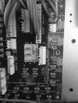
I have a external smoke detector I installed. It's on a Carrier 48HC gas pack. I'm supposed to fit the JMP3 wire and wire thru the two terminals. What wire am I sending thru this?
 

Attachments

#2 ·
Are you talking about the trouble contacts on the smoke detector? If that is the case, the relay on the smoke detector will have a Com, N.O. and N.C. contacts, refer to the wiring diagram with the detector. Wire the Com and N.C. contacts to the smoke shut down on the Carrier board then clip the jumper on the board. To test, trip the smoke detector and the unit should shut down. The jumper on the board completes the 24v control voltage so the unit operates when hooked up to the building controls. When you clip the jumper, the external set of points on the smoke detector completes the circuit unless the smoke detector trips.
 
#3 ·
The other consideration is the method being used to power the detector.

I hooked up one just like yours a few weeks ago, where someone had hacked into the 24 volt source in the unit instead of doing it correctly, as described above. Fortunately, the detector had it's own 120 volt AC source. That said, most HVAC duct detectors use a 24 volt feed from the unit to power the detector. I mention this because you then have to run four wires to the detector for the above setup: one pair to power the detector with 24 volts, and the other pair to break that circuit where the jumper is shown on the board.

I put sta-kon terminal in the wires and pushed them onto the male board terminals that you see there.
 
#4 ·
I meant "cut" not fit

William, ya I understand the NC & NO contacts on the smoke detector, which will open up if there is trouble. What low voltage wiring am I taking thru this? Am I taking my red 24v wire ( or fan wire) straight of the terminals at unit thru the contacts then back down to stat?
 
#5 ·
Time builder,

Ya the way u said it is the other way, tap into the transformer before it goes to the board, and the other way is just wire fan circuit thru contacts but that doesn't work cus fan still runs for 60 seconds or so. I'm trying to use the board as u said. My detector is 120/240/24v power. So I have 24v there at detector, and now I just take my other two wires thru the contacts on detector, to the shut down terminals and cut the jmp3 wire, so it's down internally in the board?
 
#6 ·
The jumper on the board is cut, and that connection is replaced by the contacts in the detector which are closed when the detector is in normal operation, but open when the detector goes into alarm mode.
 
#8 ·
If your only task is to break the 24 volt source, that's true.

However, I would not take the chance of that Carrier board being able to supply the power needed for the detector from that terminal. It's better to be safe, and supply an independent feed for detector power, and a set of contacts for that jumper. That way, the board cannot be presented with a overcurrent condition if the detector takes a dump.
 
You have insufficient privileges to reply here.