HVAC-Talk: Heating, Air & Refrigeration Discussion banner
1 - 20 of 75 Posts

johnl

· Professional Member
Joined
·
553 Posts
Discussion starter · #1 ·
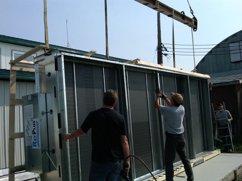
Ripping out 2 condensers that were paralelled and replacing them with one.
Condenser is for a 135hp Sabroe rack that runs 2 filacells in 2 carrot storage sheds. (around 1,500,000lbs of carrots)
Job is in progress, I will post more pics as the job progresses.

Image


Image


Image


Image


Image


Image


Image
 
Discussion starter · #4 ·
Hahaha yeah thats pretty much rabbit heaven. We are installing all of the valving for manual condenser splitting in the winter as the condenser is big time oversized when the outdoor ambient hits -30. When winter time hits and the load is low, we will shut down one side of the condenser and drain it down through a TXV and into the suction line before the accumulator. We will be starting on the piping tomorrow and I will post some more pics as we go along. Ill see if I have some pics of the rack, if not I will snap a few tomorrow.
 
Discussion starter · #6 ·
Im not sure actually, they are about 1500lbs each. One of the coils will likely be reused in something else and the other one has coil beds that are badly sagging. For someone who is o-k with taking the risk of a mid season failure they are both usable. If they were to fail in the system they were in during initial product pulldown it would have been a disaster. At best a coil like this is 3 weeks delivery. If they failed during pulldown and could not be repaired.......anyone want 1500 tons of carrots? lol. Yeah I was wrong its actually 3,000,000,000lbs of product in those sheds.
 
Discussion starter · #7 ·
Couple more quick pics, didnt get a chance to do much yesterday. We had a control line snap on another farm and drop a butload of gas so we were busy.
Image


Image


Image
 
Discussion starter · #12 ·
R-22 for now, we are just about to change another set of sheds over to R-404A. We have 9 similar systems that we service. And yes that a ****load of carrots lol. Each shed holds around 750 tons of carrots and there is 2 sheds on pretty much each system.
 
Discussion starter · #14 ·
That is proper piping practice when running a multi circuit condenser on a single system. Equal resistance through both circuits is very critical. If you pipe the liquid outlet any differently you can get liquid pushing back into one circuit and end up with wierd logging issues and need a lot more refrigerant to run the system as you end up with one condenser flooding. If you look at the old condensers, even with the way they were piped this happened and gave us headaches every winter. If you look at the piping on the new coil, everything was measured twice and piped so both circuits are 100% identical valving, pipe lengths etc.
 
that kinda makes sence??????????

i would think a tee and a 90 would be close to the same friction loss??? but hey!
i am just a service guy!!!!!!! LOL!!!!!!!!!!

either way
it looks nice

frank


That is proper piping practice when running a multi circuit condenser on a single system. Equal resistance through both circuits is very critical. If you pipe the liquid outlet any differently you can get liquid pushing back into one circuit and end up with wierd logging issues and need a lot more refrigerant to run the system as you end up with one condenser flooding. If you look at the old condensers, even with the way they were piped this happened and gave us headaches every winter. If you look at the piping on the new coil, everything was measured twice and piped so both circuits are 100% identical valving, pipe lengths etc.
 
Save
Discussion starter · #16 ·
http://www.htalk-ef.com/articles/DuPont Refrigerant Piping Handbook.pdf
Page #74 in that book shows it but doesnt talk about why.
Thats actually a very good book that I have not seen before. An hour of scanning the net for info and pics...........and I am led back to this site for what I was looking for lol.
I have been trying to think of a better way to describe what I was saying but its one of those things where if I could draw it on a piece of paper and show it to someone it would all make sense.........now to get all the white out off the monitor :p
Basically, refrigerant will follow the path of least resistance even if it is a very slight difference in resistance.
If you dropped the liquid drain line from one circuit down and 90'd towards the other, then dropped in the top of a tee with circuit #2, the circuits would have slightly different resistances to flow. While circuit #1 would have a nice easy sweep and a straight shot down the line, Circuit #2 would have a sharper turn to make and therefore more resistance. This could force more flow through Circuit 1 while causing circuit #2 to flood more because that circuit is "restricted".
Make sense?
 
Discussion starter · #18 ·
Yeah its a really good file. I started browsing through it a bit last night. Like I said I looked everywhere for a piping diagram for multi circuit condensers, split condensers etc etc and nothing. then I find a link on about page 5 of the google search to where?? This site and there is what I wanted lol.
 
Discussion starter · #19 ·
Like I said, the pressure drop issue is so critical that even though we only need to shut one side down to do the split, you must put the exact same valving on both sides. A pressure drop of even 2 or 3 psi through a valve could play with things if you dont have that same pressure drop on the other circuit. The drop out of the header before you connect also helps minimize the problem. They suggest at least 6 feet but unless you are putting your condenser on 10 foot legs its not too often you can make that work. Factory legs on this condenser were 36" and I ordered 60".
We got a little bit of work done on this job yesterday, I will post a pic just because. No big changes other than a bit of pipe and bracketry.

Image

Image
 
1 - 20 of 75 Posts
You have insufficient privileges to reply here.